
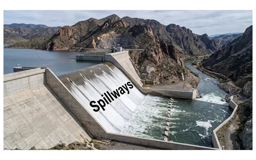
Spillways discharge water from upstream to downstream and represent the most essential structures for dams to function properly (Fig. 1). They release flood water without causing damage to the dam. The spillway often forms an integral part of the dam, constructed either at the center or along the side of the dam axis.
In some dam projects, especially earth dams, engineers locate the spillway separately, outside the dam body. A spillway consists of three parts. The head structure acts as the water inlet and includes guide walls and a bulkhead. The discharge structure carries the flow from the upper reaches to the lower parts, while the terminal structure serves as an outlet discharging to the tailwater. The spillway can operate as free flowing or under controlled flow using a gated structure.
Fig. 1: Spillway with chute and discharge of water to the downstream part of the concrete dam
What Is a Spillway?
A spillway is a hydraulic structure associated with a dam that allows excess water from a reservoir to be safely discharged downstream. It provides a designed flow path when the reservoir receives more water than can be stored or released through normal operating facilities.
A spillway is especially important during high-flow or flood conditions. Without an adequate spillway, water could rise above the safe level of the reservoir and potentially flow over parts of the dam that were not designed to carry high-velocity water.
Spillways can have different shapes and arrangements. Some allow water to flow over a crest and down an open channel, while others direct water through a shaft, conduit, or tunnel. The appropriate arrangement depends on the physical and hydraulic conditions of the site.
It is also important to understand that there is no single universal list of spillway types. Engineering organizations classify spillways in several ways, including by their control structures, flow arrangement, location, and method of operation. For example, the U.S. Bureau of Reclamation's design standards include chute, side-channel, tunnel-inlet, morning-glory, culvert, siphon, labyrinth, and other spillway arrangements.
What Is the Function of a Spillway?
The primary function of a spillway is to safely pass excess water from a reservoir to the downstream side of a dam.
Preventing Dam Overtopping
One of the most important functions of a spillway is to reduce the risk of uncontrolled water flowing over the dam. Overtopping can cause severe erosion, particularly when the dam or its foundation is not designed to withstand such flow.
Passing Floodwater
Reservoir inflows can increase rapidly during major storms or other high-water events. A properly designed spillway provides sufficient discharge capacity to pass the required design flow while maintaining acceptable reservoir levels.
Protecting the Dam
Spillways help direct water through structures designed specifically to withstand hydraulic forces. This protects the main dam structure and reduces the possibility of uncontrolled erosion.
Dissipating Flow Energy
Water flowing through a spillway can reach high velocities. Energy-dissipation structures, such as stilling basins or other terminal structures, reduce flow energy before water returns to the downstream channel.
Supporting Reservoir Operation
Depending on the type and operating arrangement, spillways may provide controlled or uncontrolled releases. Some spillways operate frequently, while others are intended primarily for unusual or emergency flow conditions. The U.S. Bureau of Reclamation distinguishes service, auxiliary, and emergency spillways according to their intended frequency and role.
Major Types of Spillways:
The five major types of spillways are described in the following subsections.
Normal Spillway:
Fig. 1 shows a normal spillway. It is a concrete structure in the form of a channel at the upper part, followed by a steep chute for accelerating water flow. The chute is rectangular or trapezoidal in shape (cross section), designed for hydraulic efficiency, with training walls constructed on either side through which the reservoir water flows to the downstream valley (Fig. 2).
In a normal spillway, the flow of water is generally regulated by a gate at the crest of the dam, which is operated to control discharge during high inflow conditions or flood events.
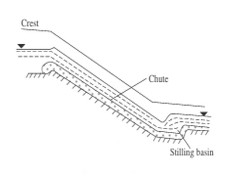
Fig. 2: Sectional view of normal spillway showing chute and stilling basin
Pipe Spillway:
In a pipe spillway (Fig. 3), a pipe passes through the dam body, usually made of steel or reinforced concrete. For low-headwater projects, constructors lay the pipe along sections of the dam using a dig-and-cover method where the head difference between upstream and downstream remains small. This spillway type suits small dams or temporary structures where cost and simplicity matter most.
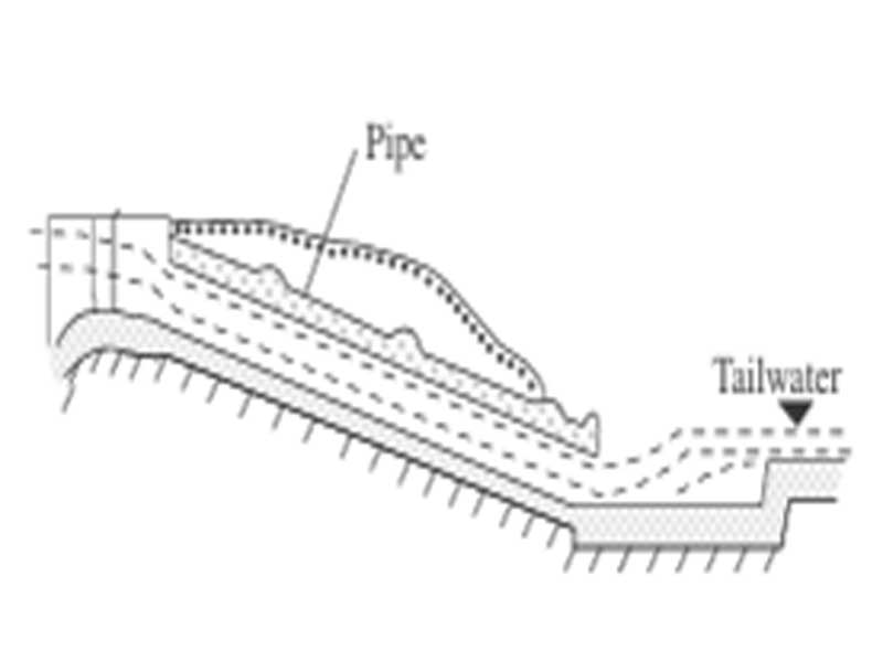
Fig. 3: Sectional view of pipe spillway showing flow of tailwater
Tunnel Spillway:
A tunnel spillway (Fig. 4) includes a tunnel puncturing the upper end that serves as the intake, while the lower (almost horizontal) end discharges water into the river or downstream channel. It includes a gate chamber that allows free flow or pressurized flow based on hydraulic needs and reservoir conditions.
Engineers often adopt tunnel spillways in narrow valleys or rocky terrains where topographic or geological factors prevent surface spillways.
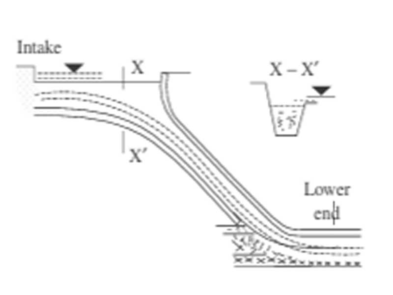
Fig. 4: Tunnel spillway from upper end into lower end with a sectional view of intake (X–X′)
Glory Hole (or Shaft) Spillway:
The glory spillway (Fig. 5) takes the form of a vertical or steeply inclined shaft. It allows water to flow freely or under pressure through the shaft into a horizontal conduit. The head structure can have a gate or remain ungated, depending on design and flow control strategies. This spillway, also called a "morning glory spillway," suits high-head dams or sites with limited space, offering an efficient and visually distinct flood discharge method.
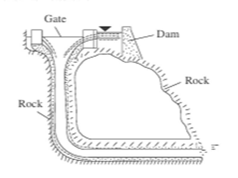
Fig. 5: Glory hole spillway with gate structure
Side Channel Spillway:
The side channel spillway structure (Fig. 6) is located towards the left or right abutment of the dam, usually on the flanks where topographic conditions are favorable. The upper and lower portions of the channel are joined by a chute for the regular and continuous flow of water from the reservoir to meet the main river at the downstream part.
The portion of the chute consists of an access channel, a head structure in the form of a trough that helps guide the flow. The head structure is a weir, generally broad-crested, designed to maintain stable overflow conditions.
In an ungated chute, the weir structure is designed with a curvilinear crest to ensure specified discharge, even under varying flow conditions, making it suitable for consistent and automatic spillway operation.
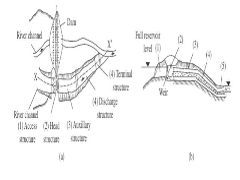
Fig. 6: Channel spillway: (a) plan of a side channel spillway; and (b) cross section along x–x
Main Components of a Spillway
Although spillway arrangements vary, many spillways contain several basic functional components.
Approach Channel
The approach channel guides reservoir water toward the spillway control structure. Its shape and alignment should provide suitable flow conditions before water reaches the crest.
Spillway Crest or Control Structure
The crest or control structure determines how water enters and passes through the spillway. Different crest shapes and control arrangements can produce different hydraulic characteristics.
Some spillways are controlled with gates, while others operate without gates. The U.S. Bureau of Reclamation's design standards classify spillways using both controlled and uncontrolled arrangements.
Chute, Conduit, or Tunnel
After passing the control section, water must be safely conveyed downstream. Depending on the spillway type, this may occur through an open chute, pipe or conduit, tunnel, shaft, or another conveyance structure.
Energy-Dissipation Structure
High-velocity water contains substantial kinetic energy. An energy-dissipation structure reduces this energy so that the downstream channel and surrounding structures are not subjected to damaging flow conditions.
Stilling Basin
A stilling basin is one type of energy-dissipation structure. It uses hydraulic conditions, including a hydraulic jump, to reduce flow velocity and energy before water continues downstream.
Outlet or Discharge Channel
The final part of the spillway system conveys discharged water safely into the downstream river, channel, or other receiving area.
Factors Affecting Spillway Selection
Selecting a spillway is an engineering decision based on several interacting conditions.
Dam Type and Size
The type, height, length, and overall configuration of the dam influence the possible spillway arrangements. A spillway suitable for a concrete dam may not be the best solution for an embankment dam.
Topography
The shape of the valley and surrounding land strongly affects how water can be routed downstream. A steep, narrow valley may favor a different arrangement from a broad valley with substantial space for an open channel.
Geology
Geological conditions are especially important when a spillway requires excavation, foundations, tunnels, shafts, or other structures in rock.
Engineers may need to consider rock strength, fractures, joints, weathering, permeability, groundwater conditions, and foundation stability. Good geological investigation can therefore help determine whether a particular spillway arrangement is practical.
Advantages and Limitations of Spillways
Spillways provide an essential safety function, but their design also involves important challenges.
Advantages
- Provide a planned route for excess reservoir water
- Reduce the risk of uncontrolled overtopping
- Help protect the dam during high-flow conditions
- Allow hydraulic energy to be managed through designed structures
- Can be adapted to different topographic and geological conditions
- Can be designed as surface, underground, controlled, or uncontrolled systems
Limitations and Design Challenges
- Large discharges can create very high flow velocities
- Improper energy dissipation can cause downstream erosion
- Spillway structures must withstand significant hydraulic forces
- Geological conditions can limit tunnel or foundation options
- Complex hydraulic arrangements may require advanced analysis or physical modeling
- Construction and maintenance can be costly
The design objective is therefore not simply to provide a passage for water. The entire spillway system must safely manage the expected hydraulic conditions from the reservoir to the downstream channel.
The main function of a spillway is to safely discharge excess reservoir water and prevent dam overtopping. It also helps protect the dam, pass floodwater, and reduce flow energy before water reaches the downstream channel.
The main components can include an approach channel, spillway crest or control structure, chute, conduit or tunnel, energy-dissipation structure, stilling basin, and outlet or discharge channel.
Spillway selection depends mainly on the type and size of the dam, topography, geology, expected water flow, foundation conditions, and downstream requirements. These factors determine which spillway arrangement can safely manage excess water.
A spillway is important because it provides a safe path for excess reservoir water. It helps prevent uncontrolled overtopping, erosion, and potential damage to the dam during high-flow conditions.
A stilling basin reduces the velocity and energy of water discharged from a spillway. It commonly uses a hydraulic jump to help protect the downstream channel and structures from excessive erosion.
Conclusion:
Spillways play a critical role in safely managing excess water in dam systems. Each type of normal, pipe, tunnel, glory hole, and side channel serves a unique purpose based on site conditions and design needs. Choosing the right spillway ensures dam safety, efficient water flow, and long-term structural stability.